PULS-B16 Setup Instructions:
The PULS-B16 is designed to replace Boumatic® pulsation controllers. The unit can support up to 16x 24V vacuum pulsators. The 7-segment LED display and control knob allow quick configuration. Indication of pulsation is shown on the dual-color pulsation LEDs which flash green when functioning correctly and red if an error such as a short circuit has occurred.
In addition, there are some hidden features that should be considered when installing for the first time, such as Power Save, Power-Up Delay, and Over-Current Threshold.
1. HARDWARE CONNECTION
The PULS-B16 can be installed to replace Boumatic® AC pulsator controllers or plunger type 24VAC systems. It can also be used in a DC environment.

AC CONNECTION (BOUMATIC®):
When configuring as in a Boumatic® style barn, connect the Molex connector to the pins 1-3 of the terminal block J1. The red center-tap wire should connect to pin 3 of J1. The other 2 wires are not polarity sensitive and can be connected to either of the secondary transformer outputs.

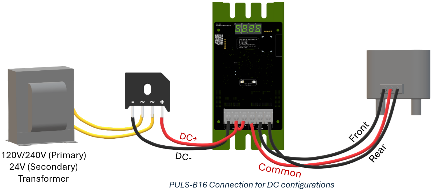
DC CONNECTION:
When configuring with a DC input, connect pins 2-3 of J1 together and connect to the positive output of the rectifier. Connect the negative pin to pin 1 of J1.
2. CONFIGURATION
Configuration setup is done using the control knob on the front of the PULS-B16. Each press of the knob will toggle through one of the configurable items.
Ratio:
Pressing the knob once will display “1.Fro” (Front Ratio). Turn the knob to adjust the ratio from 50/50 to 70/30.
Pressing the knob again will display “2.rro” (Rear Ratio). Turn the knob to adjust this value if desired.
Rate:
Pressing the knob a third time will display “3.RtE” (Rate adjustment). Turn the knob to adjust the ratio in pulses per minute (PPM) from 50PPM to 180PPM.
3. HIDDEN MENU
In some cases, there may be additional configurations necessary. The hidden menu is accessible by holding down the control knob with power disabled, and then enabling power. For firmware version 1.1 and newer the firmware version number will display for 1 second and then the hidden menu will be entered. The features can be toggled through by pressing the control knob button, adjusted by turning the control knob, and saved by pressing the button again.
Power-Save:
The hidden menu will display “1.PrS” (Power Save). Turn the knob to enable or disable the power-save option. Note, this option may not work with all pulsators, be sure to check functionality after it has been enabled if used. Default = Off
Power-Up Delay:
Pressing the knob again will display “2.Pdl” (Power Delay). In some cases, it may be desirable to have multiple pulsation controllers power-up at different times to prevent a synchronized pulsation putting too much fluctuation on the vacuum line. In such a case the controllers can be adjusted to power-on at different rates from 0-1 second in 0.1 second increments. Default = No delay
Over-Current Threshold:
Pressing the knob a second time will display “3.OCt” (Over-Current Threshold). If low-current pulsators are used or less than 8x front and rear pulsator pairs, this should be set to “Lo”. In that case an over-current condition will be detected at about 8.5A. If high power is needed set to “High” and it will allow about 17A. Default = High
System Voltage:
Pressing the knob a second time will display “4.SPL” (Supply Voltage). If a 12V system is used, set this to “12”, otherwise set to 24V (default). This sets the thresholds at which low voltage shut-down occurs. This is a safety feature and it should be set according to the supply.
4. TROUBLESHOOTING
